We can get some insight into these qualitative changes of behavior by considering systems in which the additional effects are turned on by varying a parameter. For some value of the parameter the system has enough conserved quantities to be reducible to quadratures; as we vary the parameter away from this value we can study how the divided phase space appears. The driven pendulum offers an archetypal example of such a system. If the amplitude of the drive is zero, then solutions of the driven pendulum are the same as the solutions of the undriven pendulum. We have seen surfaces of section for the strongly driven pendulum, illustrating the divided phase space. Here we crank up the drive slowly and study how the phase portrait changes.
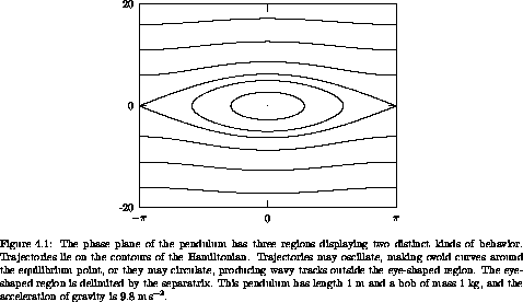
The motion of the driven pendulum with zero-amplitude drive is the same as that of an undriven pendulum. The motion of a pendulum was described in section 3.3. Energy is conserved, so all orbits are level curves of the Hamiltonian in the phase plane (see figure 4.1). There are three regions of the phase plane that have qualitatively different types of motion: the region in which the pendulum oscillates, the region in which the pendulum circulates in one direction, and the region of circulation in the other direction. In the center of the oscillation region there is a stable equilibrium, at which the pendulum is hanging motionless. At the boundaries between these regions the pendulum is asymptotic to the unstable equilibrium, at which the pendulum is standing upright. There are two asymptotic trajectories, corresponding to the two ways the equilibrium can be approached. Each of these is also asymptotic to the unstable equilibrium going backward in time.

Now consider the periodically driven pendulum, but with zero-amplitude drive. The state of the driven pendulum is specified by an angle coordinate, its conjugate momentum, and the phase of the periodic drive. With zero-amplitude drive the evolution of the ``driven'' pendulum is the same as the undriven pendulum. The phase of the drive does not affect the evolution, but we consider the phase of the drive as part of the state so we can give a uniform description that allows us to include the zero-amplitude drive case with the nonzero-amplitude case.
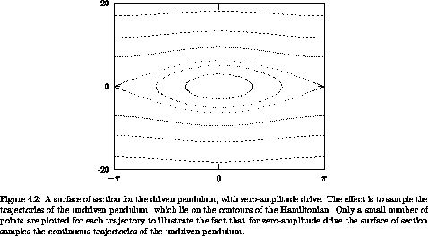
For the driven pendulum we make stroboscopic surfaces of section by sampling the state at the drive period and plotting the angular momentum versus the angle (see figure 4.2). For zero-amplitude drive, the section points are confined to the curves traced by trajectories of the undriven pendulum. For each kind of orbit that we saw in the one-degree-of-freedom problem, there are orbits of the driven pendulum that generate a corresponding pattern of points on the section.

The two stationary orbits at the equilibrium points of the pendulum appear as points on the surface of section. Equilibrium points are fixed points of the Poincaré map.
Section points for the oscillating orbits of the pendulum fall on the corresponding contour of the Hamiltonian. Section points for the circulating orbits of the pendulum are likewise confined to the corresponding contour of the Hamiltonian. We notice that the appearance of the points generated by orbits on different contours is different. Typically, if we collected more points on the surface of section the points would eventually fill in the contours. However, there are actually two possibilities. Remember that the period of the pendulum is different for different trajectories. If the period of the pendulum is commensurate with the period of the drive, then only a finite number of points will appear on the section. Two periods are commensurate if one is a rational multiple of the other. If the two periods are incommensurate then the section points never repeat. In fact, the points fill the contour densely, coming arbitrarily close to every point on the contour.
Section points for the asymptotic trajectories of the pendulum fall on the contour of the Hamiltonian containing the saddle point. Each asymptotic orbit generates a sequence of isolated points that accumulate near the fixed point. No individual orbit fills the separatrix on the section.

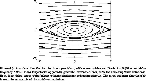
Now consider the surface of section for small-amplitude drive (see
figure 4.3). The amplitude of the drive is
A = 0.001 m; the drive frequency is 4.2  0, where
 0 = (g/l)1/2.
The overall appearance of the
surface of section is similar to the section with zero-amplitude
drive. Many orbits appear to lie on invariant curves similar to
the invariant curves of the zero-drive case. However, there are
several new features.
There are now resonance regions that correspond to the pendulum
rotating in lock with the drive. These features are found in the
upper and lower circulating region of the surface of section. Each
island has a fixed point for which the pendulum rotates exactly once
per cycle of the drive. In general, fixed points on the surface of
section correspond to periodic motions of the system in the full phase
space. The fixed point is at ±  , indicating that the pendulum
is vertical at the section phase of the drive. For orbits in the
resonance region away from the fixed point the points on the section
apparently generate curves that surround the fixed point.1 For these orbits
the pendulum rotates on average once per drive, but the phase of the
pendulum is sometimes ahead of the drive and sometimes behind it.
There are other islands that appear with nonzero-amplitude drive. In the central oscillation region there is a sixfold chain of secondary islands. For this orbit the pendulum is oscillating, and the period of the oscillation is commensurate with the drive. The six islands are all generated by a single orbit. In fact, the islands are visited successively in a clockwise direction. After six cycles of the drive the section point returns to the same island but falls at a different point on the island curve, accumulating the island curve after many iterations. The motion of the pendulum is not periodic, but is locked in a resonance so that on average it oscillates once for every six cycles of the drive.
Another feature that appears is a narrow chaotic region near where the separatrix was in the zero-amplitude drive pendulum. We find that chaotic behavior typically makes its most prominent appearance near separatrices. This is not surprising because the difference in velocities that distinguish whether the pendulum rotates or oscillates is small for orbits near the separatrix. As the pendulum approaches the top, whether it receives the extra nudge it needs to go over the top depends on the phase of the drive.
Actually, the apparent separatrices of the resonance islands for which the pendulum period is equal to the drive period are each generated by a chaotic orbit. To see that this orbit appears to occupy an area one would have to magnify the picture by about a factor of 104.
As the drive amplitude is increased the main qualitative changes are the appearance of resonance islands and chaotic zones. Some qualitative characteristics of the zero case remain. For instance, many orbits appear to lie on invariant curves. This behavior is not peculiar to the driven pendulum; similar features quite generally arise as additional effects are added to problems that are reducible to quadratures. This chapter is devoted to understanding in greater detail how these generic features arise.
1 Keep in mind that the abscissa is an angle.